
Density in Powder Metallurgy: Fundamentals, Porosity Control and Design Considerations
Understanding and controlling density in Powder Metallurgy (PM) components is one of the most important factors in the PM design process. Due to the raw material input – powder particles – PM components naturally contain residual porosity (empty voids within the component). This porosity differentiates powder metallurgy from other processes like casting or forging. Density and porosity are inverse of one another. To control density is to control porosity as well, ensuring that the powder metallurgy component achieves the exact mechanical properties we are looking for.
Let’s look at the basics of density, measurement methods, and ways to control porosity.
Density in Powder Metallurgy
Generally, density is calculated as mass ÷ volume. In powder metallurgy we analyze two density measurements to determine Relative Density.
• Measured Density
This is the measured density according to the density formula – Density = Mass ÷ Volume. This calculation includes the porosity of a PM component.
• Theoretical Density
This is density assuming no porosity – a fully dense material.
When discussing density in powder metallurgy, we use Relative Density calculated as follows:
Relative Density = (Measured Density ÷ Theoretical Density) x 100%
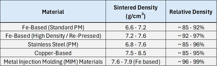
Typical Density Ranges
Effect of Density on Mechanical Properties
When density increases, porosity decreases and the following mechanical properties are improved (increased):
• Tensile Strength
• Fatigue Strength
• Impact Toughness
• Elongation (Ductility)
• Hardness (also improved via post-process operations)
However, there is a tradeoff as the advantages of porosity are minimized:
• Oil retention (self-lubrication) is sacrificed.
• The component becomes heavy, reducing the lightweight advantages provided by porous PM.
Density versus Strength
An increase in density results in an increase in tensile strength. Even a 0.1 g/cm³ increase in density can significantly improve strength.
For Fe-based PM materials, strength may change with density as follows (exact measurements will be dependent on the powder blend in use):
• Density 6.8 → TS ≈ 250 MPa
• Density 7.2 → TS ≈ 400 MPa
• Density 7.6 → TS ≈ 600 MPa
Density Distribution
Powder metallurgy components are not uniformly dense due to non-uniform powder filling, friction on the die wall during compaction and complex geometries or shapes. This can lead to some issues including local strength variation, dimensional variation and post-sintering distortion.
An ideal design for PM will take these factors into account and design for optimal uniform density. The PM designer usually adheres to the following guidelines:
• Maintain uniform wall thickness
• Avoid abrupt cross-sectional changes
• Consider density gradients (especially in pressing direction)
• Define target density based on required properties
• Multiple punch / die – PM tooling utilizes punches to achieve different features.
Methods to Increase Density
When higher density is desired, there are several solutions available:
Higher Compaction Pressure
Re-Pressing / Sizing
Sinter Forging
Infiltration
Switch to Metal Injection Molding
Measurement Methods
In powder metallurgy, density is generally measured based on two methods:
• Archimedes Method (Standard) – based on buoyancy in water.
• Geometric Method – calculated from dimensions and weight (used for quick estimates).
Summary
In powder metallurgy, density is more than just a mechanical property. It is the key parameter that determines strength, accuracy and functionality. High density results in high strength and reliability, while lower density results in lightweight components with functional porosity. Optimizing density is key to a successful powder metallurgy component design.
To discuss your design with our team of experts, click here.